10 1月 Stopper rod mechanism
The stopper rod mechanism is an integral part of the automatic stopper rod control system of a continuous casting machine which regulates the steel flow from the tundish to the mold.
It is a mechanical device with a vertically moveable stopper rod to control the flow rate. The vertical movement can be controlled either manually by a gear lever or automatically by an actuator. The stopper rod mechanism includes facilities for precision guiding, adjustment and position locking of the stopper.
The subject of this invention is a device to regulate. a tundish stopper. To be more exact, the subject of this invention is a device that regulates the position of the stopper which regulates the teeming of molten. metal through the pouring nozzle of a tundish.
Continuous casting plants are known. It is known that. the molten metal is usually discharged from a ladle into a. tundish and is teemed continuously from said tundish. an appropriate ingot mould.
So that there can be a correlation between the quantity of metal leaving the tundish and the quantity required. by the ingot mould, a stopper is employed which is immersed in the molten metal and which also serves to shut the pour-. ing nozzle so as to stop the flow at any desired moment.
It is known that said stopper is driven axially and that the accuracy of its control determines the good out-. come of the operation. The precision of the control is important since fine or minute regulation may be necessary, depending on the casting. In fact, in some cases, even small variations in the flow have a considerable effect on the. unitary volume of the ingot mould and affect the quality appreciably, causing severe problems with regard to the risk of the molten metal overflowing.
According to the invention, the stopper is connected rigidly to a substantially parallel shaft which bears a rack in an intermediate position. Said shaft is guided substantially at its ends and includes support relative to the zone comprising the rack.
Furthermore, for protective reasons a removable upper cover is envisaged which is technically insulated and can be extracted from its anchorage means.
The guides and supports for the guided shaft are supported on a plate applied to the tundish in such a way that. it can be dismantled.
A toothed sector connected to a shaft cooperates with the rack and said toothed sector serves to carry out the rough adjustment of the position of the stopper in relation to the outlet nozzle.
When rough adjustment has been carried out, an outwardly threaded sleeve connected to a controlling ring nut is clamped to the shaft parallel to and solidly connected to the stopper. If the ring nut is rotated, it is possible to move the sleeve axially even micrometrically and therewith the parallel shaft and, therefore, the stopper.
In fact, the axial displacement of the parallel shaft corresponds to an equal axial displacement of the stopper in the same direction.
The mechanisation of the regulating movement also lies within- the spirit of the invention.
Said mechanisation can be envisaged as acting on the. .toothed sector or on the axial sleeve or on both.
According to the invention, the mechanisation device envisages connection means or coupling means suitable for. independent connection during automatic operation, and means for switching off the mechanisation device during operation by hand.
The invention, therefore, is embodied in a device to regulate a tundish stopper, whereby the stopper is immersed in the tundish and is rigidly connected to a substantially parallel shaft moving parallel to the stopper; the substantially parallel shaft includes a tract with a rack cooperating with a toothed sector having a lever, said device being characterised by comprising in coordinated cooperation with the rack-wise toothed tract a reaction slide block, whereby a movable sleeve is present which can be clamped on said shaft and which cooperates with a threaded ring nut carry- . ing out axial regulation, and whereby it is possible to mechanise either the toothed sector or the movable sleeve or both of them.
With the help of the attached tables, which are given as non-restrictive examples, let us now see a preferential solution for the invention.
The tables are as follows.
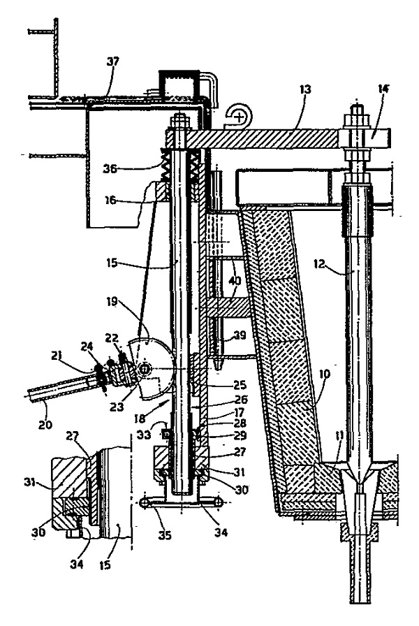
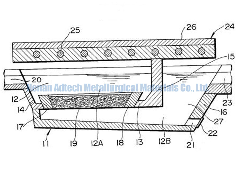
With reference to the figures, the tundish 10 has the outlet nozzle II with which the stopper shaft 12 cooperates-. The stopper shaft 12 is clamped to the rigid arm 13, advantageously within a slot 14 for sideways adjustment. At the other end of the arm 13 is anchored the substantially paral- .lel shaft 15.
The substantially parallel shaft 15 is guided at its upper end by a sleeve 16 upheld by the plate 17 screwed onto the ladle 10.
In a suitable position, there is a tract provided with a rack 18 cooperating with a toothed sector 19, which can. rotate on its axle 23 which is connected by the fork 24 to a rod 20 able to reduce the effort of operation by hand.
The fork 24 is connected to the toothed sector 19 by means of a bolt and nut, which permit the rod to lie at a . given sideways angle so as to facilitate action by the operator. The fork 24 is connected to the rod 20 with a gudgeon 21 for the purpose of easy replacement
A reaction slide block 25 on plate 17 is envisaged as cooperating with rack tract 18; in the example shown block 25 and the reaction surface 26 are flat but could also be oval, round, etc.
The reaction slide block 25 can be replaced and serves to obviate bending of the shaft 15 and, therefore, serves to maintain a good mechanical connection between rack 18. and toothed sector 19, thereby improving the manoeuvrability and life thereof.
The reaction slide block 25 has an upper layer made of a wear-resistant material; said material can be of a plastic type, such as the type known commercially under the name of Rulon-LD, for instance.
According to the invention a mechanisation organ, such as a geared motor, step motor or another type, can be visualised as being on the same axis as the toothed sector 19 and therefore with the axle 23. Said mechanisation organ can include a clutch that actuates the mechanical connection with the toothed sector 19 only if the mechanisation organ is activated, or which cuts off the mechanical connection with the toothed sector 19 when the operator is acting manually.
Instead of the clutch, there can be envisaged a coupling, a thrust-type circuit-closing switch, etc., this being un-. important for the purposes of the invention. Thus it is possible to visualise a mechanisation organ always engaged with a split ring (of the type shown with reference 33) which can be clamped, as required, by the operator on the axle 23.
In the layout shown as an example, the lower end of the shaft 15 slides in a movable sleeve 27. Said movable sleeve 27 is guided axially by the support 31 solidly fixed to the plate 17 and cooperates with a guide 29 in the tract 28, said guide being able to obviate the possibility of the rotation of the movable sleeve 27. Indeed the movable sleeve 27 has to be able to move axially but must not be able to rotate.
The movable sleeve 27 includes a split half-ring 33, which can be clamped by operating the handwheel 32. When the split half-ring 33 is clamped, it is anchored on the substantially parallel shaft 15 and becomes solidly fixed thereto.
The sleeve 27 also comprises a threaded tract 30 which cooperates with a threaded ring nut 34 unable to move axially but able only to rotate owing to the action, in our example, of the handwheel 35 solidly fixed to the ring nut 34. By acting circumferentially, therefore, on the handwheel 35, the ring nut 34 is made to rotate and itself causes axial displacement of the sleeve 27.
If sleeve 27 has the half-ring 33 clamped by means of the handwheel 32 on shaft 15, when the ring nut 34 . is made to rotate, sleeve 27 is displaced thereby, as also is the shaft 15.
By the coordinated cooperation of the ring nut 34 with the sleeve 27 it is possible to move the shaft 15 and, therewith, the stopper 12 micrometrically, thus obtaining and maintaining a very fine adjustment.
According to the invention a mechanisation organ, such. as a geared motor, step motor or another type, can be envisaged as being on the same axis as the ring nut 34 or sideways thereto and cooperating therewith 34 through transmission means. Said mechanisation organ can be disconnected or is capable of being disconnected as required by means of a. clutch, coupling or circuit-breaking switch, or else by. means of a split ring of the type shown with the reference. 33. In this way said mechanisation organ can be connected or disconnected as wished.
According to the invention, mechanisation organs can be envisaged as cooperating with both the actuation means. 19 and 34, and said organs can be linked to hand controls or automatic controls, or be connected to automatic devices monitoring the level of molten metal in the ingot mould or to controls governing the halting or ending of casting.
The upper part of the shaft 15 is visualised as being. protected by a bellows 36 and is enclosed in the insulated shield 37 which can be removed by being pulled out. Said removable shield 37, together with its insulation, shelters the operators and is equipped with two links 38 for its removal. Removal is carried out by pulling the screen 37 from above so that the pins 39 solidly fixed to it 37 come out of the guides in the supporting structure 40 of plate 17.
We have described a preferential solution here, but variants are possible. Thus it is possible to vary the proportions and sizes, or to add, remove and embody parts; the parts can be arranged in another sequence, and so on.
These and other variants are all possible for a technician in this field without departing thereby from the scope of the idea of the solution.
Related posts:
 Aluminum Silicate Stopper Cone
 Ladle Shrouds Long Nozzles
 Alumina Rod
 Filter Box for molten metal
 Tundish Upper Nozzles
 Alumina Ceramic Tundish Nozzle
 Slag Removal Machine
 Long Stoppers
 Continuous Casting Machine
 Continuous Casting and Rolling for Aluminum Alloy Wire and Rod
 Filter Bowl
No Comments