
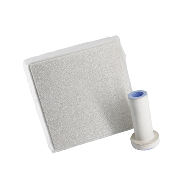
22 Temmuz Lanik Köpük Seramik Filtre
Lanik Köpük Seramik Filtre, dökümün kalite gerekliliklerine ve erimiş alüminyumdaki kalıntı sayısına göre seçilmelidir. filtrenin gözenek boyutunu belirlemek için. Filtrenin boyutu, dökülme hızı ve dökülme ağırlığı temel alınarak belirlenir.
Köpük Seramik Filtre seçerken aşağıdaki hususları göz önünde bulundurmalıyız
Döküm malzemesi/döküm sıcaklığı/döküm başlığı yüksekliği/döküm hacmi/döküm süresi
Filtrenin filtreleme etkisini sağlamak amacıyla, filtrenin yerleştirilmesi ve kapak sisteminin tasarımı da belirli teknik şartnamelere uygun olmalıdır.
Filtrenin montajı: Maksimum filtreleme verimliliği ve akış ayarlaması elde etmek için filtre, döküm parçasına mümkün olduğunca yakın bir yere yerleştirilmelidir.
Kalıba yerleştirilebilecek konum ve döküm kanalı sisteminin tasarımı gibi pratik faktörler göz önünde bulundurulduğunda, filtre genellikle döküm kanalına yerleştirilir.
Bazen filtre, döküm kanalının dibine yerleştirilir, ancak bu tavsiye edilmez.
Çünkü seramik köpük filtrenin filtreleme etkisi ve akış ayarı, döküm kanalının altından ana kanala doğru oluşan türbülanstan etkilenecektir. Filtrenin ana kanala dikey olarak monte edilmesi tavsiye edilir.
Aşırı akım hızı Lanik Köpük Seramik Filtre
Filtre akış hızı belirtilen dökümlerin çoğunda, en uygun döküm hızına karşılık gelen bir kritik döküm süresi vardır.
Döküm hızı genellikle deneyimlere dayanarak veya belirli bir dökümhanede gerçekleştirilen çok sayıda dökümün gözlemlenmesi yoluyla belirlenir.
Bazı dökümhanelerde, uygun akış hızını sağlamak amacıyla döküm sisteminin her bir parçasının kesit alanı oranını (döküm kanalının kesit alanı : dağıtıcı kanalın kesit alanlarının toplamı : iç kanalın kesit alanlarının toplamı) ayarlayarak.
Çeşitli filtre malzemeleri, erimiş demirin akışını büyük ölçüde düzenledikleri için belirli bir derecede basınç düşüşüne neden olurlar.
Filtrenin erimiş demirin akış hızı üzerindeki etkisini azaltmak için, filtrenin akış alanı, döküm kanal sisteminin akış kontrol alanından çok daha geniş olmalıdır.
Filtre tıkanmadan önce belirli bir miktarda metal akışı gerçekleşir. Tüm filtrelerin tamamen tıkanmadan önce izin verilen bir metal akış sınırı vardır.
Kalıntıların filtreden süzülmesi nedeniyle, filtrenin etkin akış alanı azalır ve akışta tıkanma meydana gelir.
Aşırı durumlarda, bu sınırın aşılması, filtreden geçen akışın tamamen durmasına neden olabilir.
Filtrenin akış kapasitesi, erimiş demirdeki katkı maddesi içeriğine, döküm sıcaklığına ve döküm sisteminin tasarımına bağlı olarak büyük ölçüde değişiklik gösterir.
Dökümhane, akış değeri ve döküm parçasının döküm ağırlığına göre filtrenin ne kadar akış alanına ihtiyaç duyduğunu belirleyebilir.
İlgili yazılar:
 Seramik köpük filtre Kanada
 Lanik Seramik köpük filtreleri
 Seramik Köpük Filtre Üreticileri
 10 Ppi Köpük Filtre
Döküm Filtresi Seramik Köpük
10 Ppi Köpük Filtre
Döküm Filtresi Seramik Köpük
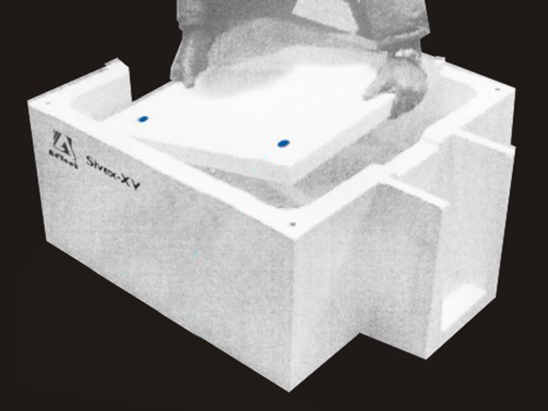 Dökümhane Seramik Köpük Filtresi
 Lanik Seramik Köpük Filtrelerini Kullanın
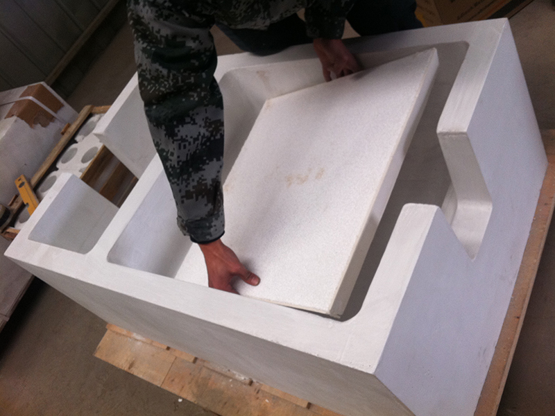 Sıvı Alüminyum filtresi
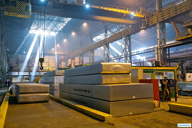 Seramik Köpük Filtre, Alüminyum, Columbia
Seramik Köpük Filtreleri Satışı
Seramik Köpük Filtre, Alüminyum, Columbia
Seramik Köpük Filtreleri Satışı
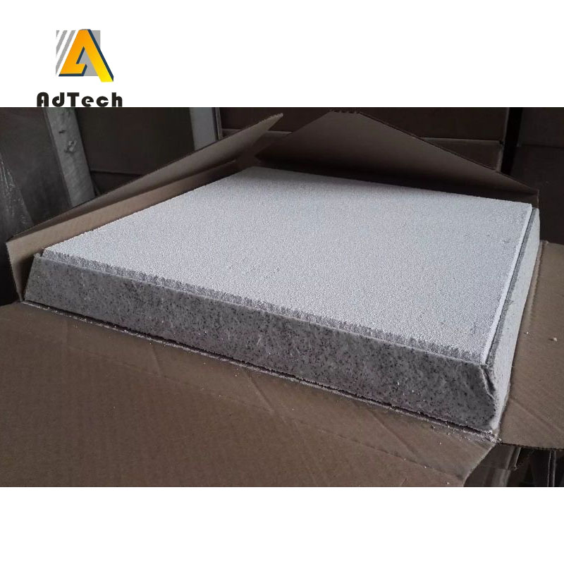 Seramik Köpük Filtrelerin Boyutlandırılması
 20 Ppi Filtre Köpüğü Satın Alın
 Metal Filtrasyonu İçin Seramik Köpük Filtre
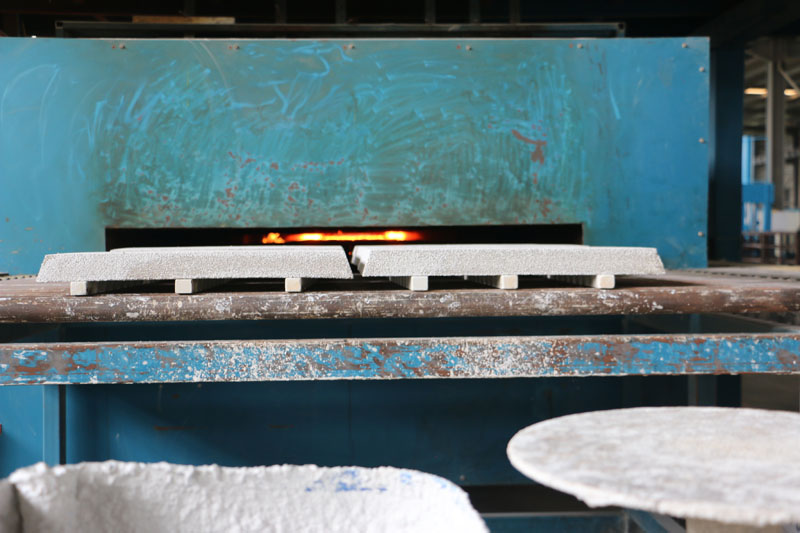 Lanik Seramik Köpük Filtreleri
Sorry, the comment form is closed at this time.