

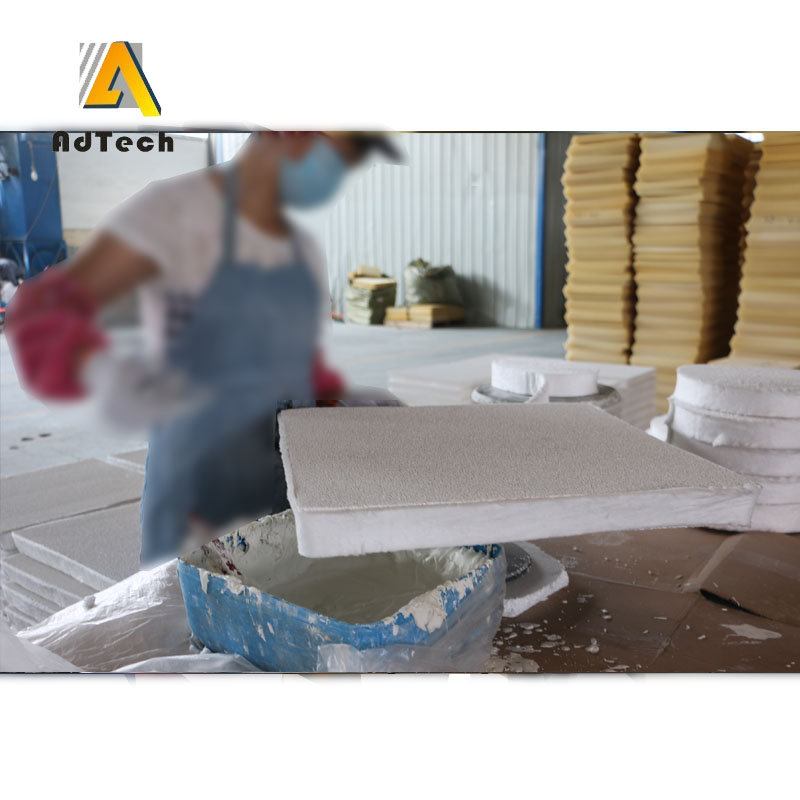
12 Eylül Seramik Köpük Filtre Nasıl Yapılır?
Nasıl Yapılır Seramik Köpük Filtre
Adtech, seramik köpük filtrenin nasıl yapıldığını size anlatacak.
Poliüretan köpüğün emprenye edilmesi için bir çözelti hazırlanması: Bir kapta potasyum tuzu ve fosforik asit, tamamen nötralize olana kadar karıştırılır.
Ardından bir alüminyum-kromofosfat bağlayıcı ilave edilir ve daha sonra, sürekli karıştırma altında, gevşek bileşenler eklenir: eriyik, alüminyum hidroksit, dolgu maddesi ve ince öğütülmüş köpük seramik filtre atığı.
Süspansiyonun karıştırılması, tamamen homojen hale gelene kadar 30-40 dakika boyunca devam eder.
Seramik Köpük Filtre Nasıl Yapılır?
Açık gözenekli elastik bir yapıya sahip poliüretan köpükten üretilen bloklar, hazır seramik şap ile emprenye edilir ve fazla süspansiyon sıkılarak çıkarılır.
Yarı mamul, 100-130 °C sıcaklıkta sabit ağırlığa ulaşana kadar kurutulur ve ardından maksimum 1280-1290 °C sıcaklıkta pişirilir.
Hazır köpük filtreler, alüminyum alaşımlarının kalıplama işlemi sırasında süzme yoluyla direnç açısından test edildi.
Önerilen köpük bloklarının bileşimleri ve prototipin fizik-teknik özellikleri, köpük filtrelerin test edilmesi sırasında elde edildi.
Önerilen çözüm, seramik köpük filtrelerin mekanik mukavemetini ve ısı direncini artırmaya olanak tanır.
Önerilen seriden elde edilen seramik köpük filtreler, daha yüksek mekanik mukavemet ve ısı direnci değerleriyle diğerlerine kıyasla üstün bir performans sergilemektedir; ayrıca, çok önemli bir nokta olarak, seramik gövdede çatlak bulunmaması nedeniyle yüksek eğilme kırılma direncine sahiptirler ve bu da temizlenen metalin kalitesini olumlu yönde etkilemektedir.
Buna ek olarak, PCF’den gelen ince öğütülmüş atıkların kullanılması, seramik köpük filtrelerin atıksız üretiminin gerçekleştirilmesini mümkün kılar.
Seramik köpük filtreler, metal dökümlerdeki safsızlıkları gidermek için kullanılır.
PPU bazlı filtreler, açık gözenekli yapıları sayesinde kirlilikleri giderir. Döküm işlemi sırasında erimiş metal, gözeneklerden geçer. Seramik köpük filtrelerde PUF, sonraki katalitik işlem için bir matris görevi görür. Köpük, seramik süspansiyonuyla kaplanır ve kurutulur. Ardından çeşitli şekillerde hazırlanan ham parçalar fırına verilir; burada ağsı poliüretan köpük matrisi yanarak yok olur ve geriye bitmiş filtrenin seramik ağ iskeleti kalır. Seramik filtre gözenek boyutları 10 ila 45 PPI/lineer inç aralığındadır.
Seramik köpük filtrenin ağ yapısı, derin filtreleme sağlar; bu sayede çok sayıda kirletici madde, başka hiçbir maddeye zarar vermeden özenle uzaklaştırılır.
Filtre, etkili filtreleme özelliğini korurken önemli ölçüde metalostatik basınca dayanabilir. Seramik köpük filtreler genellikle birincil ve ikincil alüminyum eritme işlemlerinde ve alüminyum eritme fırınlarının filtrelerinde kullanılır.
Seramik köpük filtrelerin aşağıdaki avantajları vardır
1. Erimiş metal akışlarından metalik ve metalik olmayan safsızlıkların filtrelenmesi.
2 Türbülanslı akış oluşumu sırasında oksit azalması.
3. Metal akışında artış.
4. Kötü kalıntıların ve çeşitli metal kusurlarının giderilmesi.
5. Döküm kalitesini artıran PPU filtreleri, iyi mekanik özelliklere sahiptir.
6. Üretimde hurda miktarının ve ek iş yükünün azaltılması.
7 Seramik köpük filtre çok çeşitli boyut ve şekillerde mevcuttur.
8 Tüm seramik köpük filtreler, bir ağ matrisiyle karakterize edilir; hacimlerinin tamamında birbirine bağlı, boyut ve hacim bakımından tekdüze küresel gözenekler bulunur ve bu gözenekler duvarları boyunca pencereler oluşturur. Bu yapının kıvrımlı yolları, erimiş cürufu ve diğer kirletici maddeleri geçirmekle kalmaz, aynı zamanda bunları da tutar. Sonuç olarak, bu benzersiz PPU tabanlı filtre yapısı, dökümhane pazarındaki diğer yapılara ve filtrelere kıyasla üstün metal filtreleme verimliliği sergiler.
9 Seramik köpük filtreler yüksek ısı direncine sahiptir ve erimiş metalle kolayca emprenye edilir. PPU bazlı filtrelerin üstün dayanıklılığı, yedek metal eleklere olan ihtiyacı ortadan kaldırır.
10 Döküm kalitesinin artırılması, döküm işlemi sırasında erimiş metalde oluşan cürufların filtrelenmesi ile sağlanır. PPU bazlı filtrelerin yardımıyla nihai dökümün kalitesi artırılır, metalin işlenebilirliği iyileştirilir, aynı zamanda döküm atıkları azaltılır ve hatların üretim hızları artırılır.
11 Seramik köpük filtrelerdeki gözenekler, çeşitli safsızlıklar için “tuzak” görevi görür. Bu filtre yapısı, geleneksel standart seramik filtrelere kıyasla daha avantajlıdır. Demirli metallerin erimiş kütlesi seramik köpük filtrenin yüzeyiyle temas ettiğinde, filtre kaplamasını oluşturan özel katkı maddeleri ayrışmaya başlar ve anında kesintisiz bir fayalit tabakası oluşturur. Bu kaplama yüksek sıcaklıklarda yumuşar ve viskoz hale gelir; fayalit tabakası, filtreden geçerken mikron boyutundaki kalıntıları bile tutar. Geleneksel seramik filtreler, erimiş metaldeki bu kadar çok sayıda kirliliği tam olarak tutamaz.
Üretimde poliüretan köpükten yapılmış filtreler kullandığınızda, daha temiz metal elde edecek, metalin akışkanlığını artıracak ve genel olarak nihai dökümün kalitesini yükselteceksiniz; bu da tesisin ve dökümhanenin kârında artışa yol açacaktır.
1. What is a Ceramic Foam Filter and How Does It Work?
A Seramik Köpük Filtre (CFF) is a porous, highly refractory ceramic material characterized by a three-dimensional open-cell network (reticulated structure). Designed to withstand extreme temperatures, thermal shock, and molten metal erosion, CFFs are predominantly used in continuous, semi-continuous (DC casting), and shape casting of aluminum alloys.
The Three Filtration Mechanisms
- Mechanical Straining (Screening): Large oxide skins and refractory slag particles larger than the filter pore opening are mechanically trapped on the entry face of the filter plate.
- Cake Filtration: As trapped particles accumulate at the filter surface, they form a “filter cake.” This layer subsequently acts as a secondary filter medium, capturing particles smaller than the initial pore diameter.
- Deep-Bed Adsorption: Microscopic non-metallic inclusions pass into the tortuous 3D network of the reticulated ceramic structure. Due to inertia, thermal convection, and capillary action, these inclusions contact the ceramic strut surfaces and adhere to them via physical adsorption.
Core Benefits for Aluminum Cast Houses
- Dross & Inclusion Reduction: Removes non-metallic particles down to a few microns, dramatically lowering rejection rates during X-ray testing.
- Laminar Flow Stabilization: Reduces turbulence during mold filling, minimizing secondary oxidation and air entrapment.
- Improved Mechanical Properties: Enhances yield strength, fatigue resistance, and surface finish of extruded profiles, aluminum foils, and aerospace-grade sheets.
- Machining Tool Longevity: Decreases hard spot density, significantly reducing tool wear during CNC milling and cutting operations.
2. Step-by-Step Ceramic Foam Filter Manufacturing Process
The dominant industrial method for producing high-porosity reticulated ceramic foam filters is the Organic Sponge Impregnation Method (also known as the Schwartzwalder Process). Below is the precise 6-step manufacturing workflow.
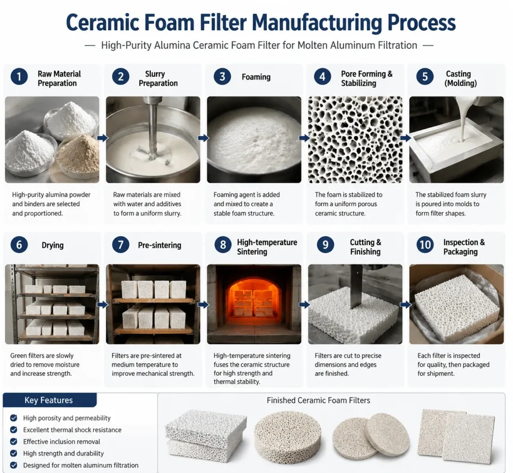
Alumina Ceramic Foam Filter manufacturing process including mixing, molding, sintering, inspection and packaging.
Step 1: Polyurethane Sponge Selection and Pre-treatment
- Base Material: Flexible, fully reticulated open-cell polyurethane (PU) foam serves as the sacrificial template.
- Pore Uniformity: The PU foam must feature uniform pore size distribution, specified in PPI (Pores Per Inch).
- Thermal Pre-treatment: The foam template is heat-treated or chemically etched to remove residual cell membranes, ensuring 100% open porosity and optimal slurry adhesion.
Step 2: Ceramic Slurry Preparation & Impregnation
- Slurry Formulation: High-purity alumina (Al2O3), silica (SiO2), binder agents (e.g., aluminum phosphate or colloidal silica), rheological additives, and anti-foaming agents are blended in a high-shear mixer.
- Viscosity Control: Slurry rheology must exhibit thixotropic behavior—flowing easily under stress while maintaining a stable structure at rest to coat foam struts evenly without clogging pores.
- Dipping Process: The pre-cut PU foam matrices are submerged in the ceramic slurry, ensuring complete wet-out of all internal struts.
Step 3: Mechanical Rolling and Excess Slurry Removal
- Squeezing Action: The impregnated foam passes through precision-calibrated roller presses to squeeze out excess slurry.
- Web Thickness Retention: Controlled clearance settings on the rollers maintain optimal ceramic strut coating thickness while preserving open passage channels.
Step 4: Controlled Drying Phase
- Moisture Evaporation: The coated foam blocks undergo drying in continuous tunnel dryers or microwave drying systems operating between 100°C and 150°C.
- Crack Prevention: Humidity and temperature profiles are carefully regulated to prevent shrinkage cracks, warpage, or structural deformation.
Step 5: High-Temperature Sintering
- Polyurethane Burn-out: As temperature reaches 300°C to 600°C in the sintering kiln, the internal polyurethane foam template burns out completely without leaving toxic carbon residue.
- Ceramic Bonding: The kiln ramps up to sintering temperatures between 1100°C and 1500°C (depending on binder and alumina purity). Thermal sintering fuses ceramic grains together, developing high mechanical strength and thermal shock resistance.
Step 6: Edge Gasket Application & Quality Inspection
- Thermal Expansion Gasket: Expandable ceramic fiber or refractory gasket strips are fitted around the edges of the filter plate to ensure a tight seal inside the filter box, preventing molten metal bypass.
- Dimensional & Visual QC: Each filter plate undergoes dimensional tolerance verification, pore density checks, and structural integrity testing.
3. Key Technical Specifications & Material Comparison
Selecting the correct ceramic material matrix is crucial to withstand thermal stress and chemical reaction with specific molten alloys.
| Property / Parameter | Alumina (Al2O3) Ceramic Filter | Silicon Carbide (SiC) Filter | Zirconia (ZrO2) Ceramic Filter |
|---|---|---|---|
| Primary Alloy Application | Aluminum, Al-Mg Alloys, Zinc | Cast Iron, Ductile Iron, Copper Alloys | Carbon Steel, Stainless Steel, Superalloys |
| Max Operating Temp | Up to 1150°C (2102°F) | Up to 1500°C (2732°F) | Up to 1700°C (3092°F) |
| Porosity Rate | 80% – 90% | 80% – 85% | 75% – 85% |
| Flexural Strength | ≥ 0,8 MPa | ≥ 1,5 MPa | ≥ 2.0 MPa |
| Termal Şok Dayanımı | Mükemmel | Superior | Outstanding |
| Kimyasal İnertlik | Highly Resistant to Molten Al | Highly Resistant to Slag | High Resistance to Corrosion |
Standard Physical Specifications (Alumina CFF for Aluminum)
- Chemical Composition: Al2O3 ≥ 85%, SiO2 ≤ 10%
- Yığın Yoğunluğu: 0.40 – 0.55 g/cm³
- Cold Compressive Strength: ≥ 0.5 MPa
- Thermal Expansion Coefficient: 7.5 × 10⁻⁶ /K
4. How to Choose the Right PPI for Aluminum Casting
Pores Per Inch (PPI) defines the pore density of a ceramic foam filter. Selecting the appropriate PPI depends on your casting method, alloy cleanliness requirements, and molten metal flow rate goals.
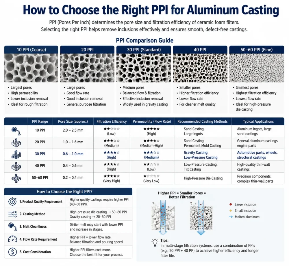
Ceramic foam filter PPI selection guide showing 10–60 PPI pore size, filtration efficiency and aluminum casting applications
PPI Selection Matrix
10 PPI to 20 PPI (Coarse Filtration)
- Primary Uses: Primary aluminum remelt, foundry ingot production, scrap recycling, and gravity casting.
- Key Characteristics: High volumetric flow rate, high dirt-holding capacity, low initial priming head requirement.
- Target Inclusions: Removes large dross particles, furnace lining flakes, and coarse oxide skins.
30 PPI to 40 PPI (Medium-Fine Filtration)
- Primary Uses: Direct Chill (DC) casting of extrusions, aluminum billets, rolling slabs, and automotive component foundries.
- Key Characteristics: Balanced performance offering efficient micro-inclusion removal alongside stable flow velocity.
- Target Inclusions: Traps intermediate non-metallic inclusions down to 30 microns.
50 PPI to 60 PPI (Ultra-Fine / Precision Filtration)
- Primary Uses: High-precision aluminum foil stock, aerospace alloys, lithographic sheet production, and ultra-thin wire drawing.
- Key Characteristics: High filtration efficiency with tight pore channels. Requires preheating and higher molten metal priming head pressure.
- Target Inclusions: Captures micro-inclusions down to 5–10 microns.
5. Application Scenarios & Filter Box Installation Best Practices
Correct installation and preheating of ceramic foam filters in casting operations are critical to preventing molten metal bypass, thermal shock breakage, and cold folds.
Step-by-Step Installation Guidelines
- Inspect Filter Box & Seating: Clean the filter bowl or launder box thoroughly. Remove residual aluminum, oxide scale, or damaged lining refractory.
- Apply Expansible Gasket: Ensure the expandable ceramic fiber sealing gasket wraps tightly around all four sides of the filter plate.
- Position the Filter: Place the filter plate flush into the filter bowl seat. Press down evenly to verify there are no gaps along the perimeter where un-filtered liquid metal could bypass.
- Preheating Sequence: Preheating the filter plate using burner flames or electric heating elements is mandatory before casting starts:
- Target Preheat Temperature: 300°C to 500°C (572°F to 932°F).
- Purpose: Prevents thermal stress cracking upon contact with molten metal and ensures instant priming without freezing.
- Priming & Flow Rate Control: Maintain an adequate metal head height (typically 50–150 mm) during initial pour to overcome surface tension and prime the filter pores.
6. Troubleshooting Common Filtration Failures
| Issue / Symptom | Root Cause Analysis | Düzeltici Eylem Planı |
|---|---|---|
| Filter Floating / Displacement | Missing or incorrectly sized edge gasket; improper filter seating inside the bowl. | Use correct ceramic fiber gasket thickness to ensure tight mechanical wedge fit. |
| Metal Priming Failure (No Flow) | Filter temperature too low during pour; selected PPI too fine for available liquid metal head pressure. | Increase filter box preheat temperature; switch to a lower PPI filter (e.g., from 50 PPI to 30 PPI). |
| Filter Structural Cracking | Severe thermal shock due to non-uniform or insufficient preheating; physical impact during loading. | Standardize burner preheat sequence; handle filter plates carefully using thermal protective gear. |
| Inclusion Bypass / Downstream Defect | Damaged edge gasket allowing molten metal to bypass filter; cracks inside filter matrix. | Inspect gasket seal prior to casting; verify cold compressive strength specifications from supplier. |
7. Frequently Asked Questions (FAQ)
Q1: What is the standard lifespan of an alumina ceramic foam filter?
Alumina ceramic foam filters are designed primarily for single-cast usage in continuous and semi-continuous casting runs. They should be replaced after every drop/cast or once maximum inclusion load capacity is reached to avoid channel clogging and pressure drops.
Q2: Why is the expandable gasket around the filter plate critical?
The ceramic fiber gasket serves two vital functions: first, it seals the perimeter to prevent liquid aluminum from leaking past the sides without being filtered; second, it expands under high casting temperatures to securely lock the filter plate in position, preventing it from floating.
Q3: How do I determine whether to use a 30 PPI or 50 PPI filter?
Base your selection on your end product quality specifications. If you are manufacturing standard industrial extrusions or billets, 30 PPI provides excellent flow efficiency and clean melt quality. If you produce foil stock, lithographic plates, or aerospace components, 50 PPI or 60 PPI is necessary to remove fine micro-inclusions.
Q4: What is the main difference between Alumina (Al2O3) and Silicon Carbide (SiC) foam filters?
Alumina (Al2O3) filters are specifically formulated for aluminum and non-ferrous alloy casting up to 1150°C. Silicon Carbide (SiC) filters exhibit much higher mechanical strength and temperature resistance up to 1500°C, making them suitable for iron, brass, and bronze foundry applications.
Technical Consultation & Procurement Solutions
Are you seeking to improve your casting yield, reduce dross rejection rates, or custom-engineer ceramic foam filter sizes for your aluminum furnace launder system?
Contact the metallurgical engineering team at AdTech today for technical datasheets, custom PPI configurations, and factory-direct volume quotes.
İlgili yazılar:
 Döküm Filtrasyonu İçin Köpük Seramik Filtre
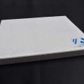 Alümina Seramik Köpük Filtre Pakistan Alüminyum
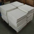 Alümina Seramik Köpük Filtreyi Kullanın
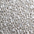 Alümina seramik köpük filtresinin iç yapısı
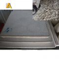 Seramik Köpük Filtre Nedir?
 Chuo Kosan Seramik Köpük Filtre
 Avustralya Köpük Seramik Filtre
 Alümina Seramik Köpük Filtre Satın Alın
 Köpük Seramik Filtre Alüminyum Sibirya
 Mozal Şirketi Seramik Köpük Filtre
 Döküm İşlemlerinde Seramik Köpük Filtreleri Kullanın
 Yüksek Alüminyum İçerikli Seramik Köpük Filtre
 Seramik Köpük Filtre UAZ Alüminyum
 Katagi Alüminyum Seramik Köpük Filtre
Sorry, the comment form is closed at this time.