

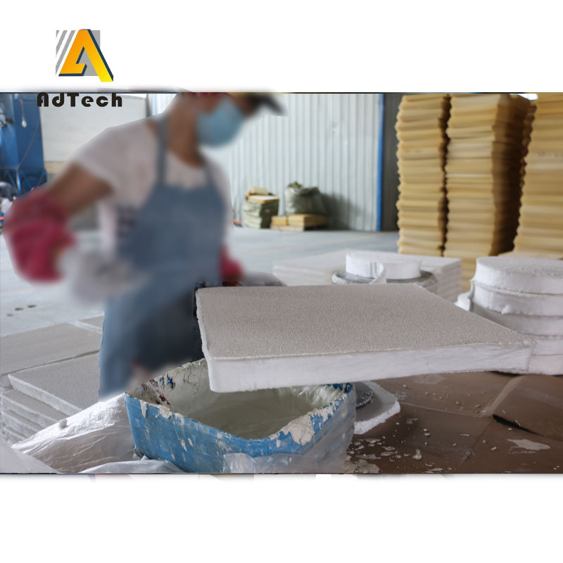
12 سبتمبر كيفية صنع مرشح رغوي خزفي
كيفية التحضير مرشح رغوي خزفي
ستشرح لك شركة «أدتيك» كيفية صنع مرشح من الرغوة الخزفية.
تحضير محلول لتشريب رغوة البولي يوريثان: يُخلط ملح البوتاسيوم وحمض الفوسفوريك في وعاء حتى يتم تحييدهما تمامًا.
ثم يُضاف مادة رابطة من فوسفات الكروم والألومنيوم، وبعد ذلك، مع التحريك المستمر، تُضاف المكونات السائبة: المادة المنصهرة، وهيدروكسيد الألومنيوم، والمواد المالئة، ونفايات مرشحات السيراميك الرغوية المطحونة ناعماً.
يستمر خلط المعلق لمدة 30-40 دقيقة حتى يتجانس تمامًا.
كيفية صنع مرشح الرغوة الخزفي؟
يتم تشريب قطع مصنوعة من رغوة البولي يوريثان ذات بنية مرنة ذات مسام مفتوحة بملاط خزفي جاهز، ثم يتم عصر الملاط الزائد منها.
يتم تجفيف المنتج شبه النهائي عند درجة حرارة تتراوح بين 100 و130 درجة مئوية حتى يصل إلى وزن ثابت، ثم يتم تحميصه عند درجة حرارة قصوى تتراوح بين 1280 و1290 درجة مئوية.
تم اختبار مرشحات الرغوة الجاهزة من حيث مقاومتها للترشيح أثناء صب سبائك الألومنيوم.
وقد تم الحصول على تركيبات الكتل المقترحة والخصائص الفيزيائية والتقنية للنموذج الأولي خلال اختبار مرشحات الرغوة.
يتيح الحل المقترح زيادة القوة الميكانيكية ومقاومة الحرارة لمرشحات الرغوة الخزفية.
تتميز المرشحات الرغوية الخزفية من المجموعة المقترحة بمعدلات أعلى من القوة الميكانيكية ومقاومة الحرارة، والأهم من ذلك، أنها تتمتع بمقاومة عالية للكسر الانحنائي، وذلك بفضل عدم وجود تشققات في الجسم الخزفي، مما يؤثر إيجابًا على جودة المعدن الذي يتم تنظيفه.
بالإضافة إلى ذلك، فإن إدخال النفايات المطحونة ناعماً من وحدة تصنيع الرغوة الخزفية (PCF) يتيح تنظيم عملية إنتاج مرشحات الرغوة الخزفية دون توليد نفايات.
تُستخدم المرشحات الرغوية الخزفية لإزالة الشوائب من المسبوكات المعدنية.
تعمل المرشحات المصنوعة من رغوة البولي يوريثان (PPU) على إزالة الشوائب بفضل بنيتها المسامية المفتوحة. وتمر مسارات المعدن المنصهر عبر هذه المسام أثناء عملية الصب. وفيما يتعلق بالمرشحات المصنوعة من الرغوة الخزفية، تعمل رغوة البولي يوريثان (PUF) كمصفوفة للعملية التحفيزية اللاحقة. يتم طلاء الرغوة بمعلق خزفي ثم تجفيفها. بعد ذلك، تُدخل القطع الأولية ذات الأشكال المختلفة إلى الفرن، حيث تحترق مصفوفة رغوة البولي يوريثان الشبكية، تاركةً وراءها إطارًا شبكيًا خزفيًا للمرشح النهائي. تتراوح أحجام مسام المرشح الخزفي من 10 إلى 45 PPI لكل بوصة طولية.
يوفر الهيكل الشبكي لمرشح الرغوة الخزفية ترشيحًا عميقًا، حيث يزيل بعناية عددًا كبيرًا من الشوائب دون ترك أي شوائب
يمكن للمرشح أن يتحمل ضغطًا معدنيًا ثابتًا كبيرًا مع الحفاظ على فعالية عملية الترشيح. وعادةً ما تُستخدم المرشحات الرغوية الخزفية في عمليات صهر الألومنيوم الأولية والثانوية، وكذلك كمرشحات لأفران صهر الألومنيوم.
تتميز مرشحات الرغوة الخزفية بالمزايا التالية
1 ترشيح الشوائب المعدنية وغير المعدنية من تدفقات المعدن المنصهر.
2. انخفاض كمية الأكسيد أثناء تكوّن التدفق المضطرب.
3 زيادة تدفق المعدن.
4. إزالة الشوائب والعيوب المعدنية المختلفة.
5. تحسين جودة الصب؛ تتميز مرشحات PPU بخصائص ميكانيكية جيدة.
6. تقليل الفاقد والأعمال الإضافية في مرحلة الإنتاج.
7 السيراميك مرشح رغوي وهي متوفرة بمجموعة متنوعة من الأحجام والأشكال.
8 تتميز جميع المرشحات الرغوية الخزفية بوجود مصفوفة شبكية، حيث تتصل المسام الكروية ذات الحجم والحجم الموحدين في جميع أنحاء حجمها، وتشكل «نوافذ» عبر جدرانها. تمر المسارات المتعرجة لهذه البنية عبر الخبث المنصهر والملوثات الأخرى وتحتجزها في آن واحد. ونتيجة لذلك، تُظهر بنية المرشح الفريدة هذه القائمة على مادة PPU كفاءة فائقة في ترشيح المعادن مقارنةً بالبنى والمرشحات الأخرى المتوفرة في سوق صناعة السباكة.
9 تتميز المرشحات المصنوعة من الرغوة الخزفية بمقاومة عالية للحرارة، كما أنها تتشرب المعدن المنصهر بسهولة. وتُغني المتانة الفائقة للمرشحات المصنوعة من مادة PPU عن الحاجة إلى شبكات معدنية إضافية.
10 يتم تحسين جودة الصب من خلال تصفية الخبث الذي يتشكل في المعدن المنصهر أثناء عملية الصب. وبمساعدة المرشحات القائمة على مادة PPU، تتحسن جودة المنتج النهائي للصب، وتزداد قابلية تشغيل المعدن، ويقل نفايات الصب في الوقت نفسه، وتزداد سرعات الإنتاج في خطوط الإنتاج.
11 تعمل المسام الموجودة في المرشحات الرغوية الخزفية كـ“مصائد” لمختلف الشوائب. ويتفوق هيكل هذا المرشح على المرشحات الخزفية القياسية التقليدية. عندما تتلامس الكتلة المنصهرة من المعادن الحديدية مع سطح مرشح الرغوة الخزفية، تبدأ الإضافات الخاصة التي يتكون منها طلاء المرشح في التحلل وتشكل على الفور طبقة متصلة من الفاياليت. يصبح هذا الطلاء لينًا ولزجًا عند درجات الحرارة العالية، ويحتجز طبقة الفاياليت حتى الشوائب التي يبلغ حجمها الميكرون أثناء مرورها عبر المرشح. لا تستطيع المرشحات الخزفية التقليدية احتجاز هذا العدد الكبير من شوائب المعدن المنصهر بالكامل.
عند استخدام المرشحات المصنوعة من رغوة البولي يوريثان في عملية الإنتاج، ستتمكن من الحصول على معدن أنقى، وتحسين سيولته، وبشكل عام تحسين جودة الصب النهائي، مما سيؤدي إلى زيادة أرباح المصنع والمسابك.
1. What is a Ceramic Foam Filter and How Does It Work?
A مرشح الرغوة الخزفي (CFF) is a porous, highly refractory ceramic material characterized by a three-dimensional open-cell network (reticulated structure). Designed to withstand extreme temperatures, thermal shock, and molten metal erosion, CFFs are predominantly used in continuous, semi-continuous (DC casting), and shape casting of aluminum alloys.
The Three Filtration Mechanisms
- Mechanical Straining (Screening): Large oxide skins and refractory slag particles larger than the filter pore opening are mechanically trapped on the entry face of the filter plate.
- Cake Filtration: As trapped particles accumulate at the filter surface, they form a “filter cake.” This layer subsequently acts as a secondary filter medium, capturing particles smaller than the initial pore diameter.
- Deep-Bed Adsorption: Microscopic non-metallic inclusions pass into the tortuous 3D network of the reticulated ceramic structure. Due to inertia, thermal convection, and capillary action, these inclusions contact the ceramic strut surfaces and adhere to them via physical adsorption.
Core Benefits for Aluminum Cast Houses
- Dross & Inclusion Reduction: Removes non-metallic particles down to a few microns, dramatically lowering rejection rates during X-ray testing.
- Laminar Flow Stabilization: Reduces turbulence during mold filling, minimizing secondary oxidation and air entrapment.
- Improved Mechanical Properties: Enhances yield strength, fatigue resistance, and surface finish of extruded profiles, aluminum foils, and aerospace-grade sheets.
- Machining Tool Longevity: Decreases hard spot density, significantly reducing tool wear during CNC milling and cutting operations.
2. Step-by-Step Ceramic Foam Filter Manufacturing Process
The dominant industrial method for producing high-porosity reticulated ceramic foam filters is the Organic Sponge Impregnation Method (also known as the Schwartzwalder Process). Below is the precise 6-step manufacturing workflow.
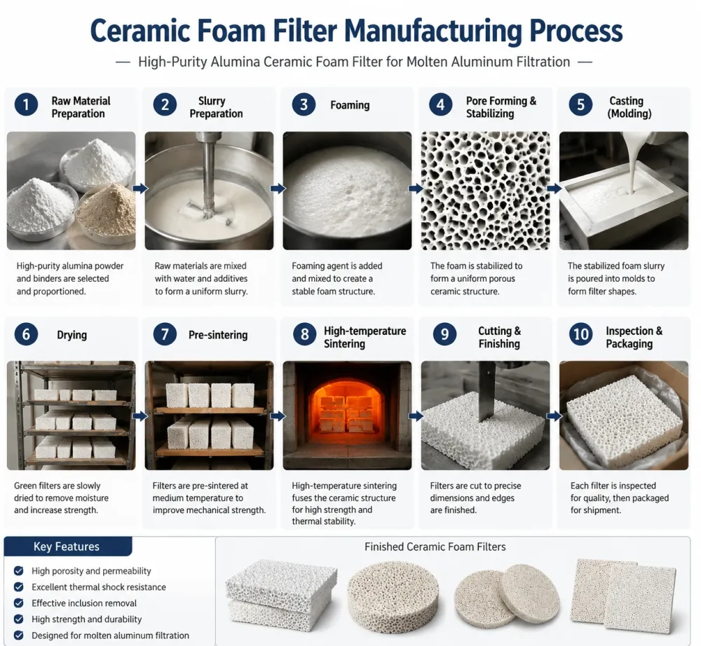
Alumina Ceramic Foam Filter manufacturing process including mixing, molding, sintering, inspection and packaging.
Step 1: Polyurethane Sponge Selection and Pre-treatment
- Base Material: Flexible, fully reticulated open-cell polyurethane (PU) foam serves as the sacrificial template.
- Pore Uniformity: The PU foam must feature uniform pore size distribution, specified in PPI (Pores Per Inch).
- Thermal Pre-treatment: The foam template is heat-treated or chemically etched to remove residual cell membranes, ensuring 100% open porosity and optimal slurry adhesion.
Step 2: Ceramic Slurry Preparation & Impregnation
- Slurry Formulation: High-purity alumina (Al2O3), silica (SiO2), binder agents (e.g., aluminum phosphate or colloidal silica), rheological additives, and anti-foaming agents are blended in a high-shear mixer.
- Viscosity Control: Slurry rheology must exhibit thixotropic behavior—flowing easily under stress while maintaining a stable structure at rest to coat foam struts evenly without clogging pores.
- Dipping Process: The pre-cut PU foam matrices are submerged in the ceramic slurry, ensuring complete wet-out of all internal struts.
Step 3: Mechanical Rolling and Excess Slurry Removal
- Squeezing Action: The impregnated foam passes through precision-calibrated roller presses to squeeze out excess slurry.
- Web Thickness Retention: Controlled clearance settings on the rollers maintain optimal ceramic strut coating thickness while preserving open passage channels.
Step 4: Controlled Drying Phase
- Moisture Evaporation: The coated foam blocks undergo drying in continuous tunnel dryers or microwave drying systems operating between 100°C and 150°C.
- Crack Prevention: Humidity and temperature profiles are carefully regulated to prevent shrinkage cracks, warpage, or structural deformation.
Step 5: High-Temperature Sintering
- Polyurethane Burn-out: As temperature reaches 300°C to 600°C in the sintering kiln, the internal polyurethane foam template burns out completely without leaving toxic carbon residue.
- Ceramic Bonding: The kiln ramps up to sintering temperatures between 1100°C and 1500°C (depending on binder and alumina purity). Thermal sintering fuses ceramic grains together, developing high mechanical strength and thermal shock resistance.
Step 6: Edge Gasket Application & Quality Inspection
- Thermal Expansion Gasket: Expandable ceramic fiber or refractory gasket strips are fitted around the edges of the filter plate to ensure a tight seal inside the filter box, preventing molten metal bypass.
- Dimensional & Visual QC: Each filter plate undergoes dimensional tolerance verification, pore density checks, and structural integrity testing.
3. Key Technical Specifications & Material Comparison
Selecting the correct ceramic material matrix is crucial to withstand thermal stress and chemical reaction with specific molten alloys.
| Property / Parameter | Alumina (Al2O3) Ceramic Filter | Silicon Carbide (SiC) Filter | Zirconia (ZrO2) Ceramic Filter |
|---|---|---|---|
| Primary Alloy Application | Aluminum, Al-Mg Alloys, Zinc | Cast Iron, Ductile Iron, Copper Alloys | Carbon Steel, Stainless Steel, Superalloys |
| Max Operating Temp | Up to 1150°C (2102°F) | Up to 1500°C (2732°F) | Up to 1700°C (3092°F) |
| Porosity Rate | 80% – 90% | 80% – 85% | 75% – 85% |
| Flexural Strength | ≥ 0.8 ميجا باسكال | ≥ 1.5 ميجا باسكال | ≥ 2.0 MPa |
| مقاومة الصدمات الحرارية | ممتاز | Superior | Outstanding |
| الخمول الكيميائي | Highly Resistant to Molten Al | Highly Resistant to Slag | High Resistance to Corrosion |
Standard Physical Specifications (Alumina CFF for Aluminum)
- Chemical Composition: Al2O3 ≥ 85%, SiO2 ≤ 10%
- الكثافة الظاهرية: 0.40 – 0.55 g/cm³
- Cold Compressive Strength: ≥ 0.5 MPa
- Thermal Expansion Coefficient: 7.5 × 10⁻⁶ /K
4. How to Choose the Right PPI for Aluminum Casting
Pores Per Inch (PPI) defines the pore density of a ceramic foam filter. Selecting the appropriate PPI depends on your casting method, alloy cleanliness requirements, and molten metal flow rate goals.
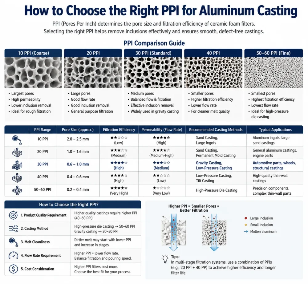
Ceramic foam filter PPI selection guide showing 10–60 PPI pore size, filtration efficiency and aluminum casting applications
PPI Selection Matrix
10 PPI to 20 PPI (Coarse Filtration)
- Primary Uses: Primary aluminum remelt, foundry ingot production, scrap recycling, and gravity casting.
- Key Characteristics: High volumetric flow rate, high dirt-holding capacity, low initial priming head requirement.
- Target Inclusions: Removes large dross particles, furnace lining flakes, and coarse oxide skins.
30 PPI to 40 PPI (Medium-Fine Filtration)
- Primary Uses: Direct Chill (DC) casting of extrusions, aluminum billets, rolling slabs, and automotive component foundries.
- Key Characteristics: Balanced performance offering efficient micro-inclusion removal alongside stable flow velocity.
- Target Inclusions: Traps intermediate non-metallic inclusions down to 30 microns.
50 PPI to 60 PPI (Ultra-Fine / Precision Filtration)
- Primary Uses: High-precision aluminum foil stock, aerospace alloys, lithographic sheet production, and ultra-thin wire drawing.
- Key Characteristics: High filtration efficiency with tight pore channels. Requires preheating and higher molten metal priming head pressure.
- Target Inclusions: Captures micro-inclusions down to 5–10 microns.
5. Application Scenarios & Filter Box Installation Best Practices
Correct installation and preheating of ceramic foam filters in casting operations are critical to preventing molten metal bypass, thermal shock breakage, and cold folds.
Step-by-Step Installation Guidelines
- Inspect Filter Box & Seating: Clean the filter bowl or launder box thoroughly. Remove residual aluminum, oxide scale, or damaged lining refractory.
- Apply Expansible Gasket: Ensure the expandable ceramic fiber sealing gasket wraps tightly around all four sides of the filter plate.
- Position the Filter: Place the filter plate flush into the filter bowl seat. Press down evenly to verify there are no gaps along the perimeter where un-filtered liquid metal could bypass.
- Preheating Sequence: Preheating the filter plate using burner flames or electric heating elements is mandatory before casting starts:
- Target Preheat Temperature: 300°C to 500°C (572°F to 932°F).
- Purpose: Prevents thermal stress cracking upon contact with molten metal and ensures instant priming without freezing.
- Priming & Flow Rate Control: Maintain an adequate metal head height (typically 50–150 mm) during initial pour to overcome surface tension and prime the filter pores.
6. Troubleshooting Common Filtration Failures
| Issue / Symptom | Root Cause Analysis | خطة الإجراءات التصحيحية |
|---|---|---|
| Filter Floating / Displacement | Missing or incorrectly sized edge gasket; improper filter seating inside the bowl. | Use correct ceramic fiber gasket thickness to ensure tight mechanical wedge fit. |
| Metal Priming Failure (No Flow) | Filter temperature too low during pour; selected PPI too fine for available liquid metal head pressure. | Increase filter box preheat temperature; switch to a lower PPI filter (e.g., from 50 PPI to 30 PPI). |
| Filter Structural Cracking | Severe thermal shock due to non-uniform or insufficient preheating; physical impact during loading. | Standardize burner preheat sequence; handle filter plates carefully using thermal protective gear. |
| Inclusion Bypass / Downstream Defect | Damaged edge gasket allowing molten metal to bypass filter; cracks inside filter matrix. | Inspect gasket seal prior to casting; verify cold compressive strength specifications from supplier. |
7. Frequently Asked Questions (FAQ)
Q1: What is the standard lifespan of an alumina ceramic foam filter?
Alumina ceramic foam filters are designed primarily for single-cast usage in continuous and semi-continuous casting runs. They should be replaced after every drop/cast or once maximum inclusion load capacity is reached to avoid channel clogging and pressure drops.
Q2: Why is the expandable gasket around the filter plate critical?
The ceramic fiber gasket serves two vital functions: first, it seals the perimeter to prevent liquid aluminum from leaking past the sides without being filtered; second, it expands under high casting temperatures to securely lock the filter plate in position, preventing it from floating.
Q3: How do I determine whether to use a 30 PPI or 50 PPI filter?
Base your selection on your end product quality specifications. If you are manufacturing standard industrial extrusions or billets, 30 PPI provides excellent flow efficiency and clean melt quality. If you produce foil stock, lithographic plates, or aerospace components, 50 PPI or 60 PPI is necessary to remove fine micro-inclusions.
Q4: What is the main difference between Alumina (Al2O3) and Silicon Carbide (SiC) foam filters?
Alumina (Al2O3) filters are specifically formulated for aluminum and non-ferrous alloy casting up to 1150°C. Silicon Carbide (SiC) filters exhibit much higher mechanical strength and temperature resistance up to 1500°C, making them suitable for iron, brass, and bronze foundry applications.
Technical Consultation & Procurement Solutions
Are you seeking to improve your casting yield, reduce dross rejection rates, or custom-engineer ceramic foam filter sizes for your aluminum furnace launder system?
Contact the metallurgical engineering team at تقنيات الإعلانات today for technical datasheets, custom PPI configurations, and factory-direct volume quotes.
مقالات ذات صلة:
 مرشح سيراميكي رغوي لترشيح السبك
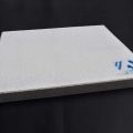 مرشح رغوي من سيراميك الألومينا، باكستان، الألومنيوم
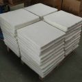 استخدام مرشح رغوي من السيراميك الألومينيوم
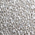 البنية الداخلية لمرشح الرغوة الخزفي المصنوع من الألومينا
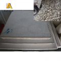 ما هو مرشح الرغوة الخزفية؟
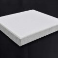 مرشح الرغوة الخزفي من شركة «تشو كوسان»
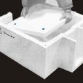 مرشح سيراميك رغوي - أستراليا
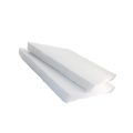 شراء مرشح رغوي من السيراميك الألومينا
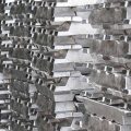 مرشح سيراميك رغوي من الألومنيوم «سيبيريا»
 مرشح الرغوة الخزفي من شركة موزال
 استخدم مرشحات الرغوة الخزفية في عمليات الصب
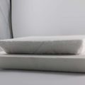 مرشح رغوي خزفي عالي المحتوى من الألومنيوم
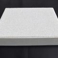 مرشح رغوي خزفي من الألومنيوم من طراز UAZ
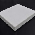 مرشح كاتاغي المصنوع من الألومنيوم والسيراميك الرغوي
Sorry, the comment form is closed at this time.