
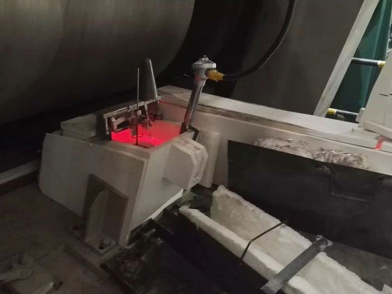
25 Aralık Çift Döküm Nozullu Erimiş Alüminyum Akış Kutusu
Çift Döküm Nozullu Erimiş Alüminyum Akış Kutusu
1. Molten Aluminum Flow Box comprising:
üst kısımda dikdörtgen şekilli bir bölüm;
a lower inverted pyramidal-shaped section; and
alt ters piramit şeklindeki bölümün alt kısmında yer alan tek parça çift nozül düzeneği.
2. Molten Aluminum Flow Box comprising:
üst kısımda dikdörtgen şekilli bir bölüm;
bir çift nozül içeren tek parça çift nozül düzeneğini barındıran alt ters piramit şekilli bölüm; söz konusu tek parça çift nozül düzeneği, alt ters piramit şekilli bölümün alt bölgesinde konumlandırılmıştır, tek parça çift nozul düzeneği, ısı iletken bir malzemeden yapılmış olup, alt ters piramit şeklindeki bölümle temastan yalıtılmış ve döküm ve döküm dışı dönemlerde, bir çift nozul aracılığıyla erimiş metal tutma ve dökme kutusu içinde bulunan erimiş metalle termal temas halindedir; ve bir çift durdurma çubuğu, bu çift durdurma çubuğunun, her bir nozülden dökülecek erimiş metalin akışını kontrol etmek için nozül çiftine geçmesi.
3. The Molten Aluminum Flow Box according to claim 2, wherein the molten metal holding and pouring box comprises an outer structural supporting layer and at least one inner insulating material layer to maintain the temperature of the molten metal within the molten metal holding and pouring box.
4. The Molten Aluminum Flow Box according to claim 2, wherein the unitary dual nozzle assembly is constructed of a material selected from the group consisting of alumina and silica.
5. The Molten Aluminum Flow Box according to claim 2, wherein each of the pair of nozzles has a conical funnel-shaped inlet and a nozzle insertion end of each of the pair of stopper rods is arranged so that when the nozzle insertion ends of the pair of stopper rods are inserted in the conical funnel-shaped inlet of the pair of nozzles to stop the flow of the molten metal through the pair of nozzles a portion of the conical funnel-shaped inlet in each of the pair of nozzles is in contact with the molten metal in the molten metal holding and pouring box.
6. The molten metal holding and pouring box according to claim 2 further comprising a unitary dual nozzle retention plate removably fastened to the bottom of the pyramidal-shaped lower section of the molten metal holding and pouring box around the outlet of each one of the pair of nozzles in the unitary dual nozzle assembly.
7. Şu molten metal holding and pouring box according to claim 6 wherein the unitary dual nozzle retention plate is removably fastened to the bottom of the pyramidal-shaped lower section of the molten metal holding and pouring box by a pair of retaining posts fastened to the bottom of the pyramidal-shaped lower section and a retention fitting passing through each one of the retaining posts below the unitary dual nozzle retention plate.
8. The molten metal holding and pouring box according to claim 7 wherein the unitary dual nozzle assembly is insulated from contact with the lower inverted pyramidal-shaped section by the combination of an insulating material surrounding the unitary dual nozzle assembly and an insulating standoff installed around each of the outlets of the pair of nozzles, the insulating standoffs disposed between the bottom of the unitary nozzle assembly and the upper side of the unitary dual nozzle retention plate.
9. A method of pouring a molten metal from a molten metal holding and pouring box with an upper rectangular-shaped section and a lower pyramidal-shaped section into a pair of molds, the molten metal holding and pouring box having a unitary dual nozzle assembly located in a bottom of the lower pyramidal-shaped section, the unitary dual nozzle assembly having a pair of nozzles, the method comprising:
transporting the pair of molds into a molten metal receiving relationship with the molten metal holding and pouring box;
holding the unitary dual nozzle assembly at the same temperature as the molten metal in the molten metal holding and pouring box; and
pouring the molten metal from the molten metal holding and pouring box through each of the pair of nozzles in the unitary dual nozzle assembly so that 75 percent of the molten metal contained in the molten metal holding and pouring box is poured into the pair of molds with no more than approximately 30 percent decrease in the rate of flow of the molten metal.
10. A method of replacing an existing unitary dual nozzle assembly in a molten metal holding and pouring box with an upper rectangular-shaped section and a lower pyramidal-shaped section for pouring molten metal into a pair of molds, the existing unitary dual nozzle assembly located in a bottom of the lower pyramidal-shaped section and having a pair of nozzles spaced apart from each other at a first distance, an insulating material surrounding the existing unitary dual nozzle assembly and a unitary dual nozzle retention plate retaining the bottom of the existing unitary dual nozzle assembly in the molten metal holding and pouring box, the method comprising the steps of:
removing the unitary dual nozzle assembly retention plate from the bottom of the existing unitary dual nozzle assembly by removing a pair of retaining fittings from a pair of retaining posts holding the unitary dual nozzle assembly retention plate to the bottom of the molten metal holding and pouring box;
removing an insulating material surrounding the sides of the existing unitary dual nozzle assembly to release the existing unitary dual nozzle assembly from the molten metal holding and pouring box;
inserting a new unitary dual nozzle assembly into the bottom of the molten metal holding and pouring box, the new unitary dual nozzle assembly having the same overall dimensions as the existing unitary dual nozzle assembly, the new unitary dual nozzle assembly having a pair of nozzles spaced apart from each other at a second distance, the second distance different from the first distance;
installing the insulating material around the sides of the new unitary dual nozzle assembly; and
installing the unitary dual nozzle assembly retention plate to the bottom of the new unitary dual nozzle assembly by inserting the pair of retaining fittings to the pair of retaining posts to hold the unitary dual nozzle assembly retention plate against the bottom of the new unitary dual nozzle assembly.
İlgili yazılar:
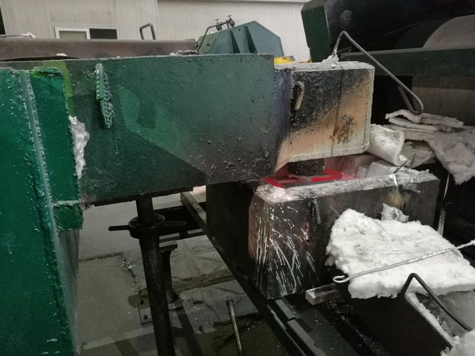 Erimiş Alüminyum Akış Kutusu
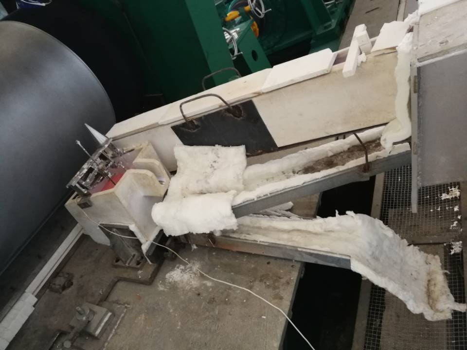 Yapışmaz alüminyum Akış Kutusu
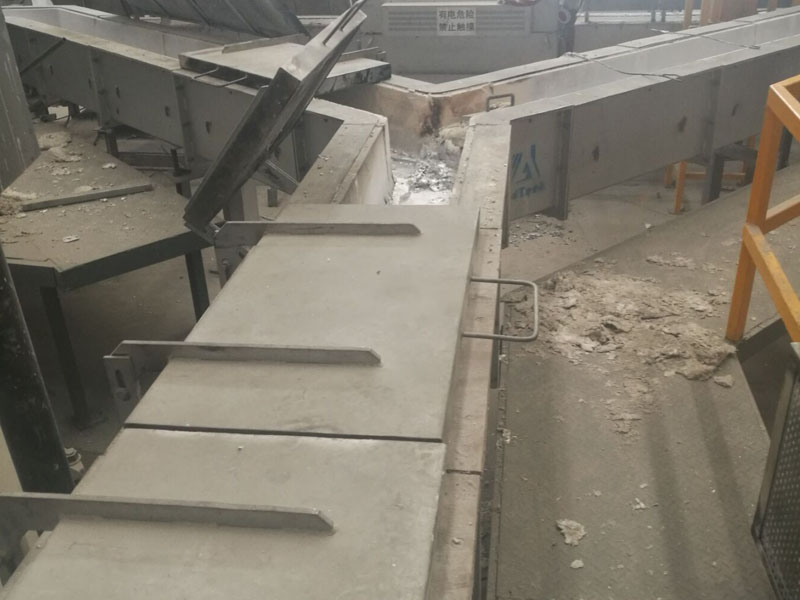 Erimiş Alüminyum Taşıma Seramik Kanalı
 Döküm nozul plakası yönlendirme parçası
 Erimiş Alüminyum Filtre Kutusu Üreticileri
 Yüksek Alümina Lifli Akış Kutusu
 Alüminyum Dökümlerin Kontrollü Dökümü
 Erimiş Metal Akışının Kontrolü
 Erimiş metal için filtre kutusu
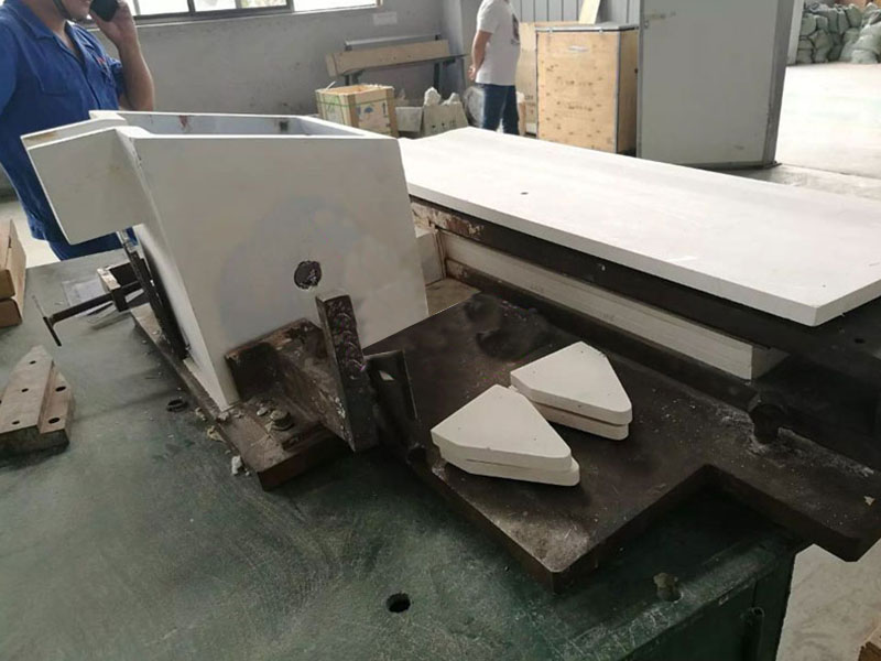 Erimiş Metal Akışının Otomatik Kontrolü
 Özel Tasarım Erimiş Alüminyum Filtre Kutusu
Döküm ve haddeleme nozulları
Özel Tasarım Erimiş Alüminyum Filtre Kutusu
Döküm ve haddeleme nozulları
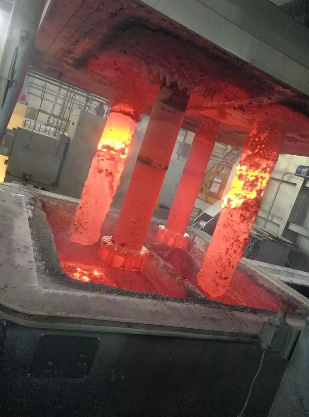 Çift Rotorlu Çevrimiçi Gaz Giderici
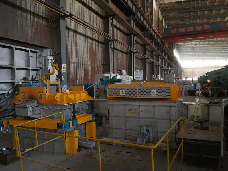 Alüminyum Endüstriyel Filtre Kutusu
No Comments