
23 Nov Degassing System For Aluminium
Degassing System For Aluminium
Degassing System For Aluminium is based on the principle that dissolved hydrogen gas will move from an area of high concentration (in the melt) to an area of low concentration (in the inert gas). Hydrogen gas disperses in molten metal as it would if it were released in any confined space. It will maintain a constant concentration throughout the melt. Hydrogen gas can migrate in liquid metal almost as fast as it can in air. Therefore, it is unnecessary to bring every ounce of metal in contact with the inert gas. The efficiency of aluminum degassing is determined by two factors, the transfer rate across the metal/gas interface and the total surface area available for transfer.
Degassing System For Aluminium bubbled specialty gases (Chlorine, Freon, or SF6) through the metal to speed the hydrogen transfer across the metal gas interface into large bubbles. There was a practical limit to hydrogen removal on humid days because as the large bubbles would break the surface, an increased surface area of metal was created which then absorbed more hydrogen from the humid atmosphere.
Chlorine was the original gas of choice but due to its hazardous nature, most foundries switched to other gases. However, many foundries have not considered the hazardous materials released by the breakdown of any specialty gas used.
Degassing System For Aluminium works on the principle of increasing the surface area of an insert gas exposed to the metal. The larger surface area increases the rate of transfer from metal to the inert gas. The smaller the bubble size for a given volume of gas, the greater is the surface area. For example, a 1” diameter bubble of gas has a surface area of 6 square inches. If the same bubble is divided into 1/16” diameter bubbles, the surface area is increased to 96 square inches. In other words, if the same volume of gas is used and the diameter of the bubbles are reduced to 1/16th the original diameter, the total surface area is increased by a factor of 16. The smaller bubbles disturb the surface of the melt less reducing additional hydrogen pickup from humid atmospheres.
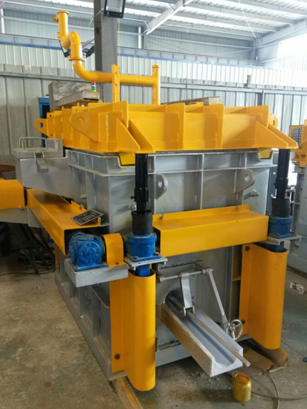
What A Degassing System Actually Does To Molten Aluminium
Aluminium in liquid form absorbs hydrogen from moisture in the atmosphere, from damp charge material, from combustion byproducts, and even from oils and greases left on scrap. Hydrogen solubility in liquid aluminium sits far higher than in solid aluminium, meaning that as the metal cools and solidifies, the excess hydrogen has nowhere to go except into microscopic voids inside the casting. Those voids show up later as porosity, and porosity is the number one reason castings get rejected in x-ray inspection or fail under load.
A degassing unit solves this by bubbling a purge gas through the melt. The purge gas has almost zero hydrogen partial pressure, so hydrogen dissolved in the aluminium diffuses into the bubbles and rises out with them. The smaller and more numerous the bubbles, the more surface area is available for that diffusion, which is why rotor design and bubble dispersion matter so much more than raw gas flow rate.
We’ve seen operators assume that simply cranking up gas flow solves everything. It doesn’t. Past a certain point, large bubbles just punch through the melt too fast to pick up hydrogen efficiently, and you waste inert gas without improving melt quality. That’s a mistake we correct constantly when auditing customer setups.
Why Hydrogen Removal Alone Isn’t The Whole Story
Most modern rotary degassing units also strip out non-metallic inclusions such as oxides, spinels, and carbides. The rising gas bubbles act like tiny flotation devices, sweeping inclusions upward into the dross layer where they can be skimmed off. This dual function is why a rotary unit paired with a ceramic foam filter downstream has become close to standard practice at any cast house producing automotive or aerospace-grade components.
How Hydrogen Gets Into Aluminium In The First Place
| Contamination Source | Typical Contribution | Practical Control Method |
|---|---|---|
| Furnace atmosphere moisture | High | Dry burner combustion, proper furnace sealing |
| Wet or oily scrap charge | High | Scrap preheating, degreasing before charging |
| Refractory moisture | Moderate | Bake-out procedure after refractory relining |
| Fluxes with moisture content | Moderate | Store flux in sealed, heated containers |
| Holding furnace exposure time | Cumulative | Minimize holding time, cover melt surface |
| Transfer ladle atmosphere | Low to moderate | Preheat ladles, use ladle covers |
We put this table together after years of running hydrogen content checks across different plant configurations. The pattern is consistent: scrap moisture and furnace atmosphere account for the majority of hydrogen pickup, and no amount of downstream degassing fully compensates for sloppy upstream melt handling. A degasser is a correction tool, not a substitute for good melting practice.
Main Types Of Aluminium Degassing Systems
There isn’t one universal degassing technology. Different production volumes, alloy grades, and budget levels call for different equipment.
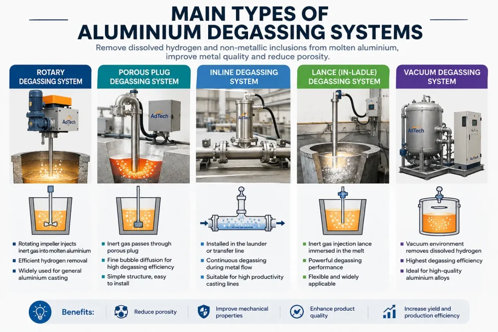
Main types of aluminium degassing systems for molten aluminium treatment, including rotary, porous plug, inline, lance and vacuum degassing equipment.
Rotary Impeller Degassing Units
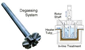
This is the dominant technology in die casting, sand casting, and permanent mold operations. A motor-driven shaft with a graphite or CFC (carbon fiber composite) rotor spins at the bottom of a treatment vessel or directly in the holding furnace, shearing the incoming purge gas into thousands of fine bubbles. Rotor speed usually runs between 400 and 600 rpm depending on rotor geometry and melt volume.
Porous Plug And Lance Systems
Porous plugs fitted into the base of a ladle or furnace release gas as fine bubbles without any moving parts. Lances are simpler still, essentially a refractory-coated pipe dipped into the melt to release gas from the bottom. Both methods are cheaper upfront but generally less efficient than rotary units because bubble dispersion is harder to control without mechanical shearing.
In-Line Degassing Units For Continuous Casting
In-line units sit directly in the metal launder or trough feeding a continuous casting line or DC (direct chill) casting process. They’re built for constant throughput rather than batch treatment, using multiple rotors or chambers to treat metal as it flows rather than as it sits.
| System Type | Typical Efficiency (Hydrogen Reduction) | Capital Cost | Best Suited For |
|---|---|---|---|
| Rotary impeller (single rotor) | 60–75% | Moderate | Batch furnaces, die casting cells |
| Rotary impeller (multi-rotor in-line) | 75–90% | High | Continuous casting, wire rod, sheet ingot |
| Porous plug | 40–55% | Low | Small foundries, low-volume operations |
| Lance | 30–45% | Very low | Basic operations, temporary fixes |
| Vacuum degassing | 80–95% | Very high | Specialty alloys, aerospace-grade billet |
We list vacuum degassing here for completeness, but it’s rarely used for standard aluminium alloys because the cost-to-benefit ratio doesn’t make sense outside of very high-spec aerospace or defense billet production.
Rotary Degassing Units In Detail: Components And Function
A rotary degasser looks simple from the outside, a motor sitting on top of a shaft, but the engineering underneath determines whether it performs well for six months or six years.
The Rotor And Shaft
Rotors used to be almost exclusively graphite, and graphite is still common for cost reasons. CFC rotors and shafts last considerably longer, resist thermal shock better, and hold their geometry longer under continuous rotation, which keeps bubble dispersion consistent over the life of the component. We’ve replaced graphite shafts every three to four weeks in high-throughput operations, whereas a well-specified CFC shaft in the same environment often lasts two to three months before replacement.
The Motor And Drive System
Variable frequency drives (VFDs) let operators tune rotor speed to melt volume and alloy type rather than running a fixed speed regardless of batch size. This alone can cut gas consumption by 15-20% because operators stop over-purging small batches.
Gas Supply And Flow Control
Nitrogen is the default purge gas for general-purpose aluminium alloys because it’s inexpensive and widely available from on-site generators or bulk tanks. Argon is used where slightly better hydrogen removal is needed, since argon’s lower thermal conductivity and different bubble behavior can improve contact time in certain alloy systems. Argon-chlorine mixtures were common decades ago for their inclusion removal properties, but environmental and worker safety regulations have pushed most operations away from chlorine-based blends toward chlorine-free fluxing combined with mechanical rotary degassing.
Refractory Vessel Or Treatment Chamber
For units that operate outside the main furnace, the treatment vessel needs refractory lining rated for repeated thermal cycling. Poor refractory choice here is an underappreciated failure point, we’ve seen vessels crack within weeks because the lining specification didn’t match the actual cycling frequency of the operation.
Measuring Whether Degassing Is Actually Working
Buying equipment is only half the job. Knowing whether it’s performing correctly matters just as much, and this is where a lot of plants fall short.
Reduced Pressure Test (RPT)
The RPT remains the most widely used shop-floor method. A metal sample solidifies under reduced atmospheric pressure, exaggerating any porosity so it becomes visible and measurable through density comparison or visual grading against reference standards. It’s inexpensive, fast, and gives operators a rough but actionable read on melt quality.
First Bubble Test And AlSCAN / LAIS Units
Instruments like AlSCAN or LAIS give a real hydrogen content reading in milliliters per 100 grams of aluminium within a few minutes, which is far more precise than the RPT. We recommend these instruments for any operation producing structural or safety-critical parts, because RPT results can be influenced by sample cooling rate and operator interpretation in ways that instrumented readings are not.
| Test Method | Time To Result | Precision | Typical Use Case |
|---|---|---|---|
| Reduced Pressure Test | 10–15 minutes | Low to moderate | General shop floor quality checks |
| AlSCAN / LAIS (first bubble) | 3–5 minutes | High | Structural and safety-critical castings |
| Telegas | 5–10 minutes | High | Continuous process monitoring |
| Laboratory sample analysis | Hours to days | Very high | Certification, R&D, alloy development |
Target hydrogen levels typically sit below 0.15 to 0.20 ml/100g for high-integrity castings, though the exact number depends on alloy grade, wall thickness, and end-use requirements. Anything above 0.3 ml/100g in a critical part is generally considered a red flag.
Choosing The Right Degassing System For Your Operation
We get asked constantly by purchasing managers and plant engineers which system to buy, and the honest answer is that it depends on production volume, alloy mix, floor space, and existing furnace setup rather than any single “best” answer.
Questions Worth Asking Before You Buy
- What’s the daily melt throughput in kilograms or metric tons, and how much does it fluctuate seasonally?
- Are you treating metal in a static holding furnace, a transfer ladle, or a continuous flow launder?
- What alloy grades are running through the line, and do any have unusually tight hydrogen specifications?
- What’s your current scrap or reject rate attributable to porosity, and what would a 1% reduction be worth annually?
- Do you have space and utility connections (compressed inert gas, electrical supply, cooling water for the motor) for a permanent installation?
- What’s your maintenance team’s familiarity with rotary equipment, graphite/CFC components, and refractory work?
Matching System To Production Scale
| Production Volume | Recommended System | Rationale |
|---|---|---|
| Under 500 kg/hour | Porous plug or single-rotor unit | Lower capital cost matches lower throughput needs |
| 500 kg to 3 tons/hour | Rotary impeller, VFD-controlled | Balances cost with consistent quality control |
| 3 to 10 tons/hour | Multi-station rotary or in-line degassing | Handles volume without treatment bottlenecks |
| Over 10 tons/hour (continuous casting) | In-line multi-rotor system | Built for continuous flow, minimal downtime |
Common Operational Problems And How We’ve Solved Them
Every plant we’ve consulted with eventually runs into a similar handful of problems, and most of them trace back to maintenance neglect or incorrect process settings rather than equipment defects.
Excessive Rotor Wear
Rotors wearing down faster than expected usually means rotor speed is set too high for the alloy viscosity, or the rotor material doesn’t match the operating temperature range. Switching from graphite to CFC, or simply dialing back rpm by 10-15%, often extends service life noticeably without hurting degassing performance.
Inconsistent Hydrogen Readings Across Batches
This almost always comes down to inconsistent gas flow rate or a rotor that’s degraded unevenly, creating uneven bubble dispersion. We’ve traced more than one “mystery” quality problem back to a flow meter that drifted out of calibration months earlier and nobody noticed.
Dross Buildup And Metal Loss
Aggressive rotor speeds or excessive treatment time can churn the melt surface enough to generate more dross than necessary, which means metal loss and extra cleanup labor. Slightly reducing treatment time while confirming hydrogen targets are still met usually resolves this without sacrificing quality.
Refractory Cracking On The Treatment Vessel
Thermal cycling between batches, especially in operations that treat intermittently rather than continuously, stresses refractory linings. Preheating the vessel before each cycle and avoiding rapid temperature swings extends refractory life considerably.
Maintenance Practices That Keep A Degassing Unit Running Longer
We treat maintenance scheduling as being just as important as the initial equipment specification, because even the best rotary unit underperforms badly on a neglected maintenance schedule.
| Maintenance Task | Recommended Frequency | Why It Matters |
|---|---|---|
| Rotor and shaft inspection | Daily to weekly (throughput dependent) | Catches wear before it affects bubble quality |
| Gas flow meter calibration | Monthly | Prevents drift that skews degassing consistency |
| Motor bearing lubrication | Per manufacturer schedule | Avoids premature motor failure |
| Refractory vessel inspection | Weekly | Identifies cracking before metal breakout risk |
| VFD and control system check | Quarterly | Confirms speed settings remain accurate |
| Full unit teardown and rebuild | Annually or per usage hours | Resets wear on seals, bearings, and couplings |
Operations running three shifts, seven days a week obviously need tighter inspection intervals than a plant running a single shift with lighter volume. We adjust these intervals for clients based on actual usage hours logged by the control system rather than calendar time alone, which tends to be a more honest measure of component fatigue.
Cost Considerations And Return On Investment
Purchasing managers care about upfront price, but the more useful number is cost per ton of metal treated over the equipment’s service life.
Capital And Operating Cost Breakdown
A basic single-rotor unit with manual controls typically costs less upfront than a VFD-controlled, PLC-integrated multi-rotor in-line system, but the operating savings from better gas efficiency and rotor life on the higher-spec unit often close that gap within 18 to 30 months in medium-to-high volume operations.
| Cost Category | Basic Rotary Unit | Advanced VFD/PLC Rotary Unit |
|---|---|---|
| Approximate equipment cost | Lower | 40-70% higher than basic unit |
| Annual gas consumption cost | Higher (less precise control) | Lower (optimized flow per batch) |
| Rotor/shaft replacement frequency | More frequent | Less frequent (better speed control) |
| Labor for manual adjustment | Higher | Lower (automated recipe control) |
| Typical payback period on cost difference | N/A | 18-30 months in medium/high volume plants |
Reject Rate Reduction As The Real ROI Driver
The biggest financial argument for upgrading degassing equipment usually isn’t gas or rotor savings, it’s scrap reduction. If porosity-related rejects drop from 4% to 1.5% on a plant producing several hundred tons monthly, the value of that alone frequently exceeds the entire equipment cost within the first year. We always recommend purchasing decisions be modeled around reject rate improvement first, and consumable savings second.
Safety And Environmental Compliance
Handling inert and reactive gases in a foundry environment carries real risk that shouldn’t be glossed over in equipment selection.
Inert Gas Asphyxiation Risk
Nitrogen and argon are non-toxic but displace oxygen in enclosed spaces. Any pit, trench, or basement area near a degassing station needs oxygen monitoring and proper ventilation, and we insist on this being part of any installation checklist regardless of how routine the operation seems.
Regulatory Movement Away From Chlorine
Older degassing practices relying on chlorine gas or hexachloroethane tablets have fallen out of favor across most regulated markets because of worker exposure limits and emissions rules. Nitrogen and argon rotary degassing combined with proper fluxing has become the accepted replacement, and most equipment manufacturers no longer design new units around chlorine compatibility at all.
Noise And Ergonomic Factors
Rotary motors and gas flow can add meaningful noise exposure over an eight-hour shift. Hearing protection requirements and enclosure design around the treatment station are worth confirming with any equipment supplier before installation, not after.
Where Aluminium Degassing Technology Is Headed
We’ve watched the technology shift meaningfully over the past decade, and a few trends are worth flagging for anyone planning equipment purchases with a five-to-ten-year horizon.
Sensor Integration And Real-Time Hydrogen Monitoring
Newer systems increasingly pair the degassing unit with inline hydrogen sensors feeding data directly into the plant control system, allowing gas flow and rotor speed to adjust automatically rather than relying on periodic manual RPT checks. This closes the loop between measurement and correction in a way that manual systems simply can’t match.
CFC Component Adoption Continuing To Grow
As CFC pricing has come down relative to a decade ago, more mid-size operations that previously stuck with graphite for cost reasons are switching over, driven by the total cost of ownership math rather than upfront price alone.
Energy Efficiency Pressure
With energy costs rising in many regions, VFD-driven motors and optimized gas flow profiles are being adopted not just for quality reasons but because they measurably cut electricity and gas consumption per ton treated, which matters more each year as utility costs climb.
Frequently Asked Questions
What is the main purpose of a degassing system in aluminium casting?
It removes dissolved hydrogen gas from molten aluminium before casting, preventing porosity defects that weaken castings and cause rejection during quality inspection.
Which gas is typically used in aluminium degassing?
Nitrogen is the most common choice due to cost and availability, with argon used in applications requiring slightly improved hydrogen removal or specific alloy handling requirements.
How often should the rotor and shaft be replaced in a rotary degasser?
Graphite components often need replacement every three to six weeks in high-throughput operations, while CFC rotors and shafts commonly last two to three months or longer under similar conditions.
Can degassing alone guarantee porosity-free castings?
No. Degassing addresses hydrogen-related porosity, but shrinkage porosity from poor gating or solidification design requires separate process corrections in mold or die design.
What hydrogen content level is considered acceptable for structural castings?
Most structural applications target below 0.15 to 0.20 ml/100g, though exact thresholds vary by alloy specification and end-use load requirements.
Is vacuum degassing better than rotary impeller degassing?
Vacuum degassing achieves higher hydrogen removal efficiency but comes with significantly higher capital and operating costs, making it practical mainly for specialty or aerospace-grade alloy production.
How long does a typical degassing treatment cycle take?
Batch treatment in a holding furnace typically runs 5 to 15 minutes depending on melt volume, rotor speed, and target hydrogen level, while in-line systems treat metal continuously as it flows.
Does degassing remove non-metallic inclusions as well as hydrogen?
Yes, rising gas bubbles carry inclusions such as oxides toward the melt surface where they collect in the dross layer and can be skimmed off, making degassing a dual-purpose melt cleaning step.
What causes inconsistent degassing results between batches?
The most common causes are uncalibrated gas flow meters, uneven rotor wear affecting bubble dispersion, and inconsistent treatment time between operators or shifts.
Is chlorine gas still used in modern aluminium degassing?
Rarely in regulated markets. Environmental and worker safety rules have largely replaced chlorine-based degassing with nitrogen or argon rotary systems combined with appropriate fluxing agents.
Related posts:
 Aluminium Hydrogen Degassing Equipment
 Aluminium Degassing With Nitrogen
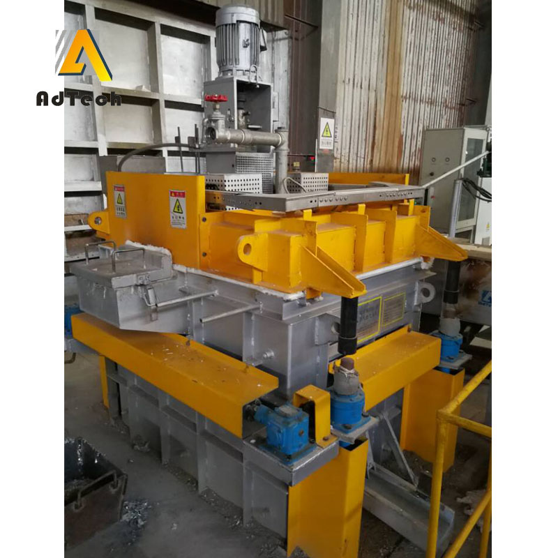 Metal Metallurgy Casting Foundry Aluminium Degassing Treatment
 Degassing In Aluminium Casting
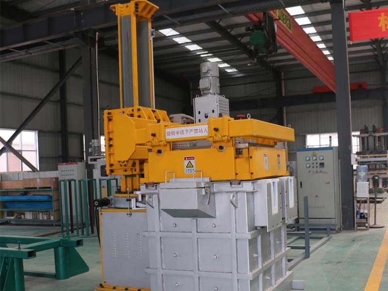 Degassing Aluminium
 Aluminum Degassing Methods
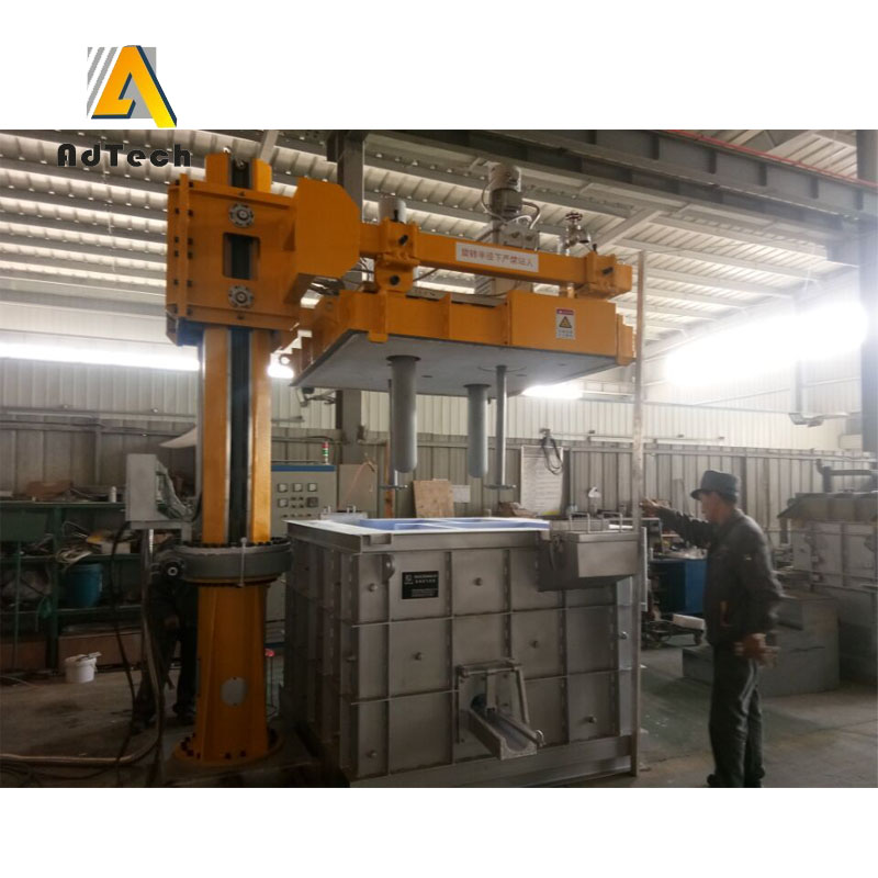 Degassing In Aluminium Casting
 Aluminium Degassing Equipment
 Aluminium Degassing Methods
 Online Degassing Unit for High Purity Aluminium
 Degassing Aluminum
 Degassing System For Aluminium
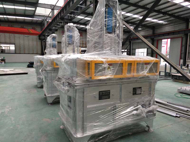 Rotary Degassing Machines
Double Rotor Degassing Euipment
Rotary Degassing Machines
Double Rotor Degassing Euipment
Vavaiya Ketan
Posted at 06:09h, 06 Februaryhi
i want to purchase vacuum degasing system for aluminium. my procuction capacity 2T/ Hr. max. and i am using induction melting furnace.
can you suggest your product which is suitable for this application if yes, please provide me technical specifications and techno commercial proposal for the same alos send me some photos and video for the same for batter understanding.
Also provide detailed GA dwg. for the same.